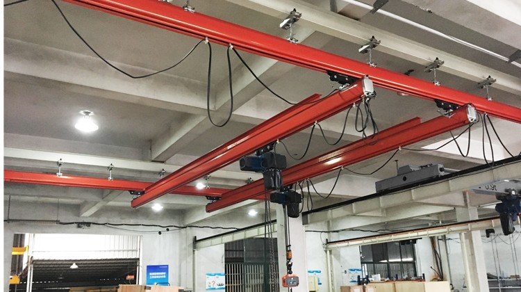
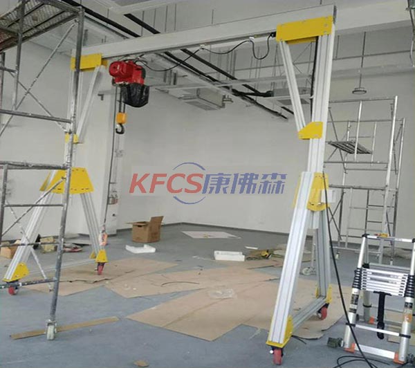
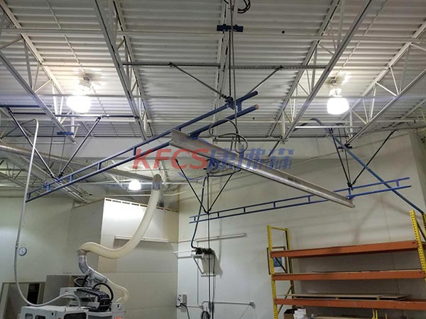
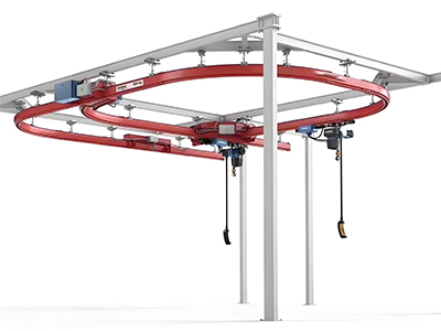
Installation steps of clean room aluminum alloy track standard components
Installation steps of clean room aluminum alloy track standard components
1. Suspension of the track (installation of a vertical hanging device with a spring clamp)
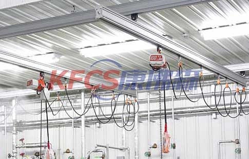 1. Install the upper suspension on the rail-bearing beam and the suspension clip on the track, and place the two ball-strand long nuts in the ball sockets of the upper suspension and the suspension clip respectively. All connecting bolts must be tightened to the specified torque.
2. Screw the threaded suspension rods into the two ball-stretched long nuts of the upper suspension and rail suspension clamps respectively, until the spring clamp can pass through the long hole of the ball-stranded long nut and the lateral hole of the threaded suspension rod, according to the specified torque. Tighten the bolts on the suspension clamps to suspend the light rail. If the threaded hanger must be shortened and cut off according to the installation needs, a new transverse hole must be machined at the end of the screw. The diameter of the transverse hole and the distance from the end are: LHJⅠ: the diameter is 3.2mm, and the distance is 5mm. LHJⅡ: The diameter is 4.0mm and the distance is 6mm.
3. The hexagonal socket wrench with universal joint is especially suitable for this bolt connection.
4. There should be no steps on the wheel tread at the track interface, and there should be no resistance when the trolley is pushed through the joint. The vertical deviation of the track connection should be less than 0.3mm.
5. It should be ensured that the bolts are tightened reliably and evenly according to the specified torque. If the joint bolts are tightened at one end more than the other, the track will bend; when several tracks are suspended, they must be aligned in the same horizontal plane.
6. Use the hanging screw to screw into the upper and lower ball nuts to adjust the depth of the track to the same level, and the level difference between the adjacent lifting points is less than 10mm.
2. Installation of end cover with buffer and built-in buffer
1. Install the trolley group, cable carriage or cable trolley and built-in buffer into the track.
2. To protect the cable carriage, install a built-in buffer in the rail on the power supply side, and drill holes on the top of the rail (distance from the end of the rail ≤ the required number of cable carriages). Two holes with a distance of 32mm and a diameter of 9.5mm with respect to the axis of the LHJI track; two holes with a distance of 50mm and a diameter of 9.5mm with the axis of the KHJII track.
3. Close the rail ends with end caps with buffers. Tighten the three connecting bolts of the end cover according to the specified torque to ensure the safe operation of the trolley.
3. Installation of turnouts and turntables
1. All hanging devices for hanging turnouts and turntables must be evenly loaded. The installation and hanging method is the same as the rail hanging.
2. The track joint bolts of turnouts and turntables should not be subjected to shear force, for example, there is no force in any direction near the end of the track that needs to be connected. This can be checked by loosening the connecting bolts, after loosening the bolts, the relative position of the track joint should be aligned.
3. For manual turnouts and turntables, the height of the rope handle should be set according to the needs of use. Turnouts or turntables should be inspected to ensure that their moving parts operate correctly and are secured in place, and that there should be no steps in the tread of the trolley at the track junction.
4. Assemble the LHJⅡ-R built-in trolley line track
1. LHJⅡ-R built-in trolley line track docking. First, check whether the conductor interface at the end of the track corresponds to each other, and then insert the short ends of the five trolley wire connecting pins into the conductor interface of the same track to connect the tracks. (Note that the long end of the trolley wire connecting pin should correspond one-to-one with the other track conductor interface, and dislocation is not allowed.)
2. All LHJⅡ-R built-in trolley wire tracks should be connected to the ground wire painted in yellow and green with the middle conductor when connecting to the power supply. The phase order of the wiring should be L1, L2, ground, L3 and spare.
3. The maintenance section of the collector trolley is a mechanism for checking and disassembling the collector trolley. In order to ensure the safety of the maintenance section, one set of rail hanging devices should be installed at the two ends of the maintenance section less than 300mm.
4. If a built-in buffer needs to be installed in the LHJⅡ-R built-in trolley line track, it must be installed on the side of the track. Drill two holes with a diameter of 9.5mm and a hole spacing of 50mm in the vertical direction of the side of the track. The buffer must be in contact with the track tread to ensure there is enough space from the sliding contact line.
5. For the non-terminal of LHJⅡ trolley line track, use self-tapping screws to tighten the trolley line terminal sheath to the trolley line (grounding protective conductor), and then use the track end cover with buffer to close the track.
6. The collector trolley should always be located between two running trolleys or between the two wheels of a long trolley. This prevents it from colliding with other carts or end bumpers. When placing the collector trolley in the track, make sure that the phase wires L1, L2 and L3 are connected correctly. When used with a double beam trolley, the collector trolley can be installed between the front and rear wheels of the trolley.